
- FORWARD AND REVERSE MOTOR CONTROL DIAGRAM FOR CRANE DRIVERS
- FORWARD AND REVERSE MOTOR CONTROL DIAGRAM FOR CRANE DRIVER
- FORWARD AND REVERSE MOTOR CONTROL DIAGRAM FOR CRANE FULL
Just cut a 1"x1" piece of the can using scissors - bend up the sides a little, and drill an 5/32" hole to mount it. You can alternately make your own heatsink out of a piece of aluminum can. The heatsink should be installed on the transistor with the "Enable" pin using a #6 bolt and nut (screw it on tight!). I've verified the Radio Shack 276-1363 heatsink can be installed without re-soldering everything (you may need to bend stuff a little). The TIP120 is rated at 5 amps - but will overheat without a heatsink if run this hard continuously. A TIP120 on its own provides a super-simple way to do single-direction motor control. This gives them much higher "gain" - meaning they can use a very small current to switch a much larger current. These transistors are actually two transistors chained together into one. This project uses TIP120 "Darlington" transistors. I chose the one featured in this project since Radio Shack stocked it.
FORWARD AND REVERSE MOTOR CONTROL DIAGRAM FOR CRANE DRIVER
It should be possible to build a version of this driver that supports lower voltages by swapping out the relay with one having a lower "pickup" voltage. Fortunately - the component most likely to burn out is the transistor with the "Enable" pin - so you're only out a $1.50.
FORWARD AND REVERSE MOTOR CONTROL DIAGRAM FOR CRANE DRIVERS
Unlike many commercial motor drivers - this driver does not have any "protection" - so if you abuse it too much - it will fail. It's rated at 130% of nominal - or 15.6v. The relay's coil seems to dictate the maximum voltage this circuit can handle. If you're having problems with the controller refusing to reverse - it may be that your input voltage is too low. We'll go through all the connections one-by-one.

This is listed as 9.6v - but I've found it to function properly as low as about 7.5v.ĭon't worry if the schematic doesn't make total sense. The minimum voltage to drive this circuit is determined by the "pickup" voltage of the relay.

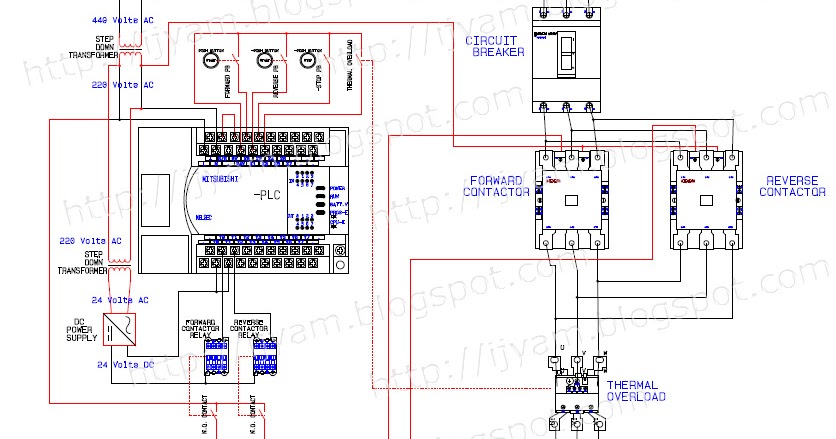
The enable pin may be switched on and off very quickly for PWM (pulse width modulation) speed control.īoth control pins are connected to the microcontroller via 220 Ohm resistors to limit current. The "Base" of the second TIP120 is the "Enable Pin" - turning it on causes the motor to actually run. This is used to turn the motor on and off. The "Base" of the first TIP120 is the "Direction Pin" - turning it on and off switches the direction of the motor.Ī second TIP120 switches power to common on the relay. Since the microcontroller can't quite produce enough current to drive the relay - a transistor (TIP120) is used to switch it on and off. This in effect reverses the wiring whenever the relay is turned on or off. The motor is connected to both normally closed and normally open (in reverse) sides of the relay. Does not requireįriends, if you like this information, please comment and share it.This circuit uses a DPDT (Double Pole Double Throw) relay to switch which direction the motor is turning. Power circuit has not been depicted in the picture in the circuit to run the direct direction from the direct direction to the direct direction to the direct direction. It is shown in the circuit picture, the power circuit of both types of circuits is the same.
FORWARD AND REVERSE MOTOR CONTROL DIAGRAM FOR CRANE FULL
Contactor K2 NO connection leaving his magnetic quCL Keep current and the motor is provided in the L2 L1 元 in order to run in full straight direction from the opposite direction to run the circuit once the circuit is used in the lift train Toli Crane etc. It is necessary to turn off the motor in the opposite direction in the opposite direction, without off-off Contractor K1 NC Combination Contactor does not allow K2 to be prevalent, thus when the motor began to roam in the opposite direction, then the Contactor K2's NC Connection Contactor K1 does not allow it to be called Interlocking, after offering the motor from the off-push button, the motor can be run in the opposite direction by Push Button R. The motor runs in the direct direction by providing the Face in the direct direction by providing the Face in the direct direction of Contractor K1 but also leaving his magnetic quil. This circuit is depicted in the picture given further in the Contractor K1 Push Button F. It is enough to change, based on this, two types of circuits are created to change the direction of rotating a three-face motor. We have learned that the Face Face Motors I have great importance if the face sequence is not well, then it will start roaming in the opposite direction, i.e.


 0 kommentar(er)
